

Article Updated: 22 Mar 2022
C-MEDIA CM6206 is a cheap and solid performance audio codec chip supporting 16 bit / 48 kHz audio, stereo* MIC and LINE-IN inputs. Works out of the box on Windows 10 operating system with stock drivers. Great for hobby recordings & measurements (e.g. using Virtins Multi-Instrument / Oscilloscope, ARTA / LIMP, etc.), despite the fact it has only 16 bit A/D converters and 48 kHz sampling rate! 99.999% of us humans can’t hear the difference between standard 16 bit / 44.1 kHz and 24 bit / 192 kHz audio anyway thanks to low-pass filtering, interpolation and human hearing characteristics.
PART 1: C-MEDIA CM6206 5.1 External USB Audio Sound Card Line-In Bass Extension Frequency Response Modification
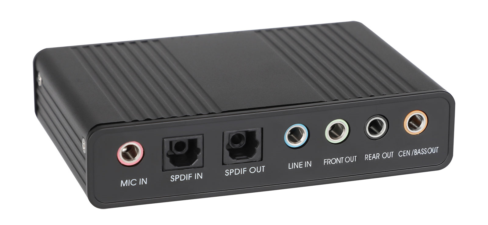
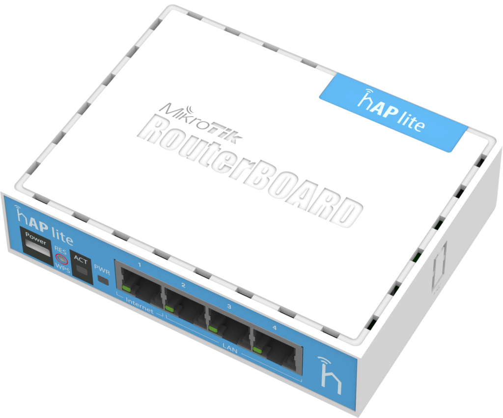
C-MEDIA CM6206 5.1 USB Audio Sound Card – Product Photo
C-MEDIA CM6206 – THE PROBLEM
If you wish to start a YouTube or Twitch career, transfer your old audio cassette recordings or vinyl collection to your computer, C-MEDIA CM6206 External USB Sound Card is a very nice solution in case you use a modern laptop without integrated multi-channel audio card and dedicated Line-In or MIC inputs. This card can be bought really cheap on Amazon, AliExpress, BangGood and similar online stores, and have it delivered for free in few days or weeks.
Paired with a cheap studio-like condenser microphones such as BM-800 or Neewer NW-700 you can really step-up the quality and get yourself going in the right direction for well under $50 budget.
Of course, we cannot possibly compare it to the more advanced and higher-quality Realtek, Intel, Nvidia or AMD HD Audio codecs (supporting up to 5.1 / 7.1 / 24-32 bit / 192-384 kHz with absolutely flat frequency response in 20-20 kHz range and beyond), but for this price we can’t and don’t complain. Plus, unless it’s a desktop computer, current laptop computers using them only have stereo headphones output and (maybe) single mono DC-biased MIC input (sometimes hidden in a single 4-wire 3.5 mm socket), and do not support analog stereo LINE or MIC inputs that we need!
However, engineers who designed and manufactured this sound board crippled LINE-IN analog recording inputs frequency response in low / bass section by putting very small coupling capacitors! Why oh why ???
CM6206 hardware is perfectly capable going all the way down to a sub-hertz (less than 1 Hz) flat frequency response if desired / required. You can even bypass input AC coupling capacitors to enable DC input, with some precaution (useful for audio oscilloscope applications and DC signal measurements e.g. using Daqarta software).
C-MEDIA CM6206 audio codec is used in many different sound cards, including 7.1 surround models. It supports separate Headphone output, mute, rec mute, digital volume controls, dual mono MICROPHONE inputs and more! Of course, in this 5.1 model not all the features are used (obvious cost reduction saving on external parts and components), but what can you expect from a $5 or $10 sound card? More expensive $20 models come with 7.1 audio, dedicated headphones output, dual MIC and LINE-IN inputs, Volume and Mute controls, but those are not really essential, as you can achieve the same in software, although they can be convenient as dedicated hardware buttons.
In essence, this is a very solid audio card for the money!
C-MEDIA CM6206 5.1 External USB Audio Sound Card – Line-In Frequency Response Measurements
[1] Right-Mark RMAA without modification (loopback audio Line-In <-> Line-Out)
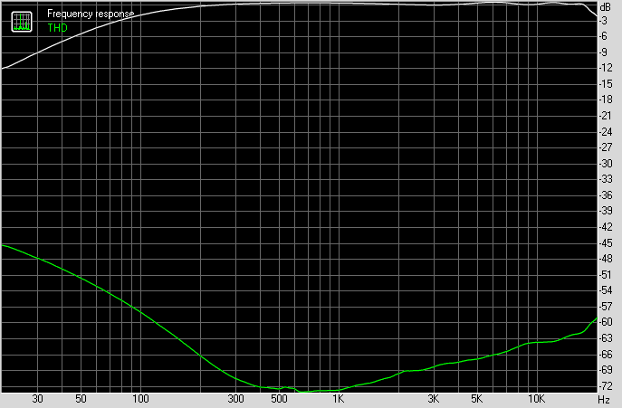
RMAA C-MEDIA CM6206 5.1 USB Audio Card 16-bit, 48 kHz Loopback Line-In Frequency Response Spectrum + THD
[2] Right-Mark RMAA without modification (loopback audio Line-In <-> Line-Out)
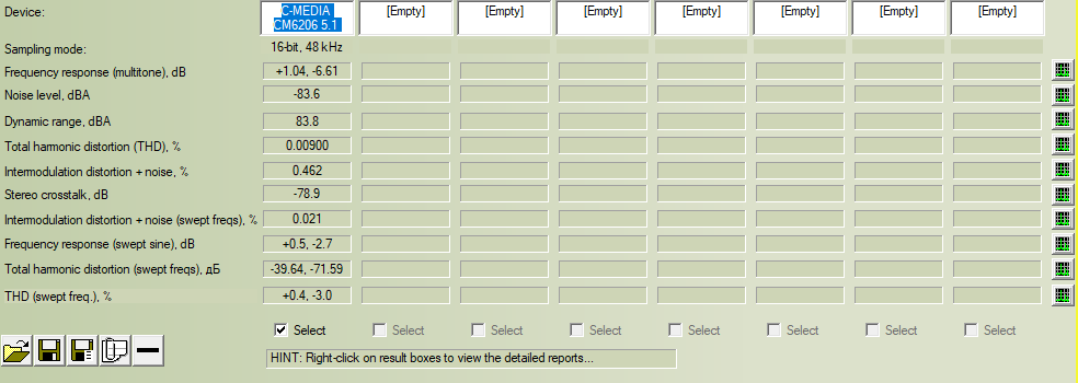
RMAA C-MEDIA CM6206 5.1 USB Audio Card 16-bit, 48 kHz Loopback Line-In Frequency Response Spectrum TEST OVERVIEW
[3] without modification (ARTA FR1 CH loopback audio Line-In <-> Line-Out)
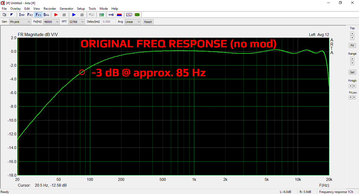
ARTA #1-1 C-MEDIA CM6206 5.1 USB Audio Card Line-In ORIGINAL 20Hz-20kHz
[4] with 4.7 uF input coupling capacitors modification (ARTA FR1 CH loopback audio Line-In <-> Line-Out)
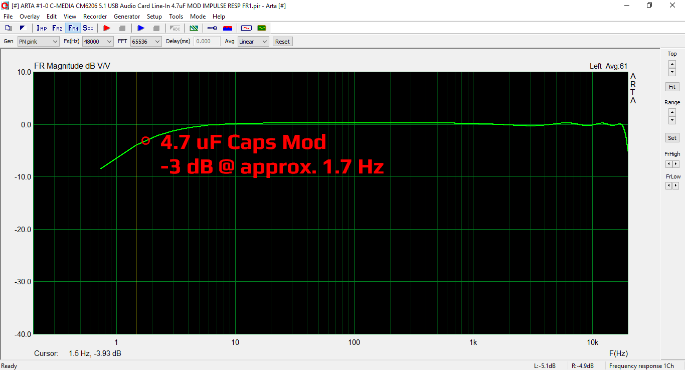
ARTA #1-2 C-MEDIA CM6206 5.1 USB Audio Card Line-In 4.7uF MOD 0.2Hz-20kHz -3dB Marker
[5] with 1 uF input coupling capacitors modification (ARTA FR1 CH loopback audio Line-In <-> Line-Out)
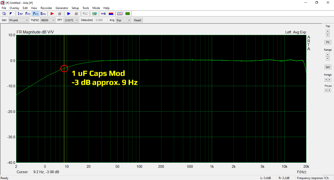
ARTA #1-3 C-MEDIA CM6206 5.1 USB Audio Card Line-In 1.0uF MOD 0.2Hz-20kHz -3dB Marker
C-MEDIA CM6206 5.1 External USB Audio Card Line-In Modification Video Tutorial
In this video I have upgraded input coupling capacitors with larger values and improved frequency response considerably! In the end of the video is a line-in recording example using C-MEDIA CM6206 5.1 External USB Sound card with and without this modification compared to the original audio, along with the frequency response charts.
Watch Video Tutorial:
Used SMD capacitors: 1608 A (0603) XR7 type
C-MEDIA CM6206 5.1 External USB Audio Sound Card – High Resolution PCB Board Photos with Annotations
Note: click on photos to load full resolution images
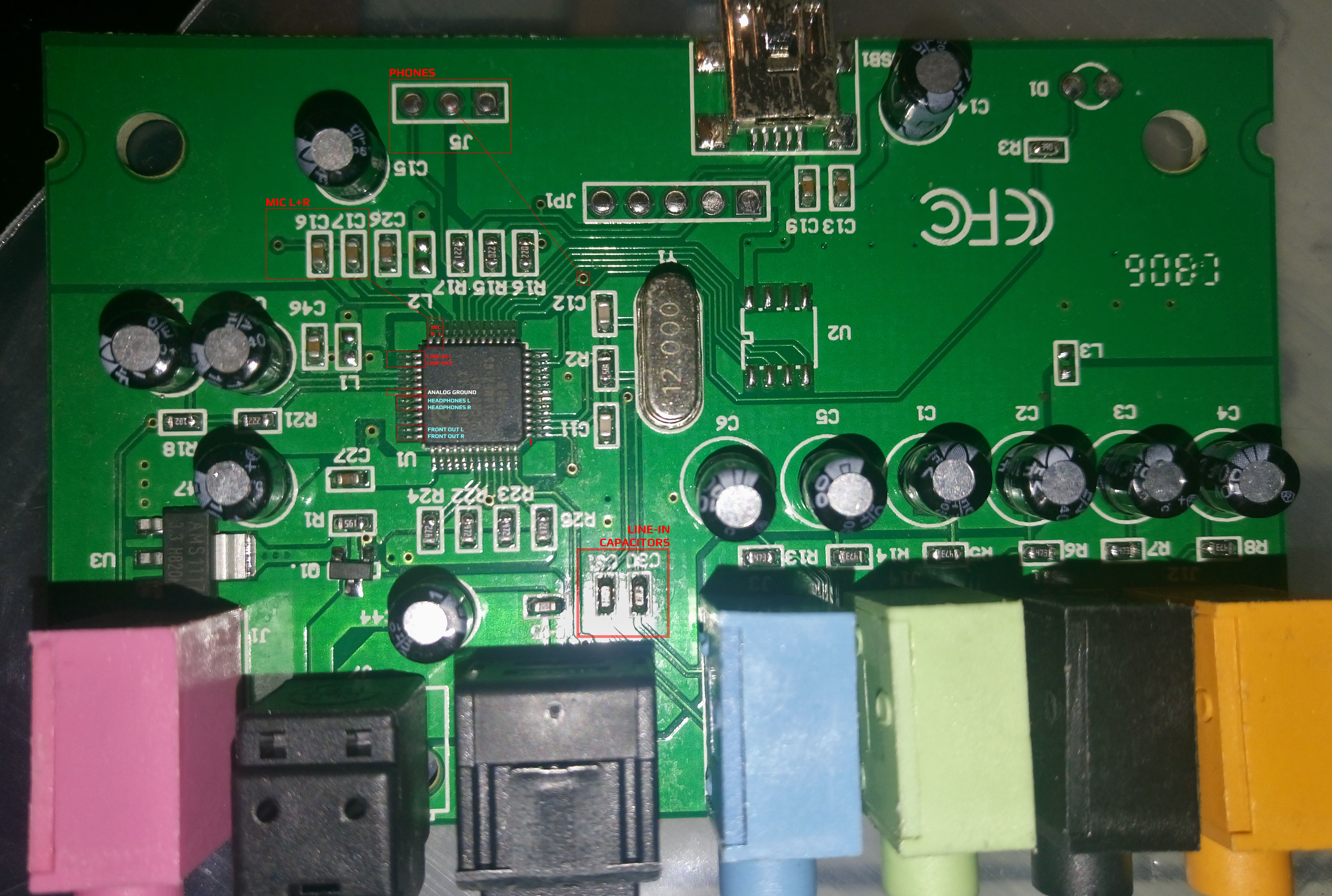
C-MEDIA CM6206 5.1 USB Audio Card – TOP & BOTTOM PCB Layers Overlay – Top Side
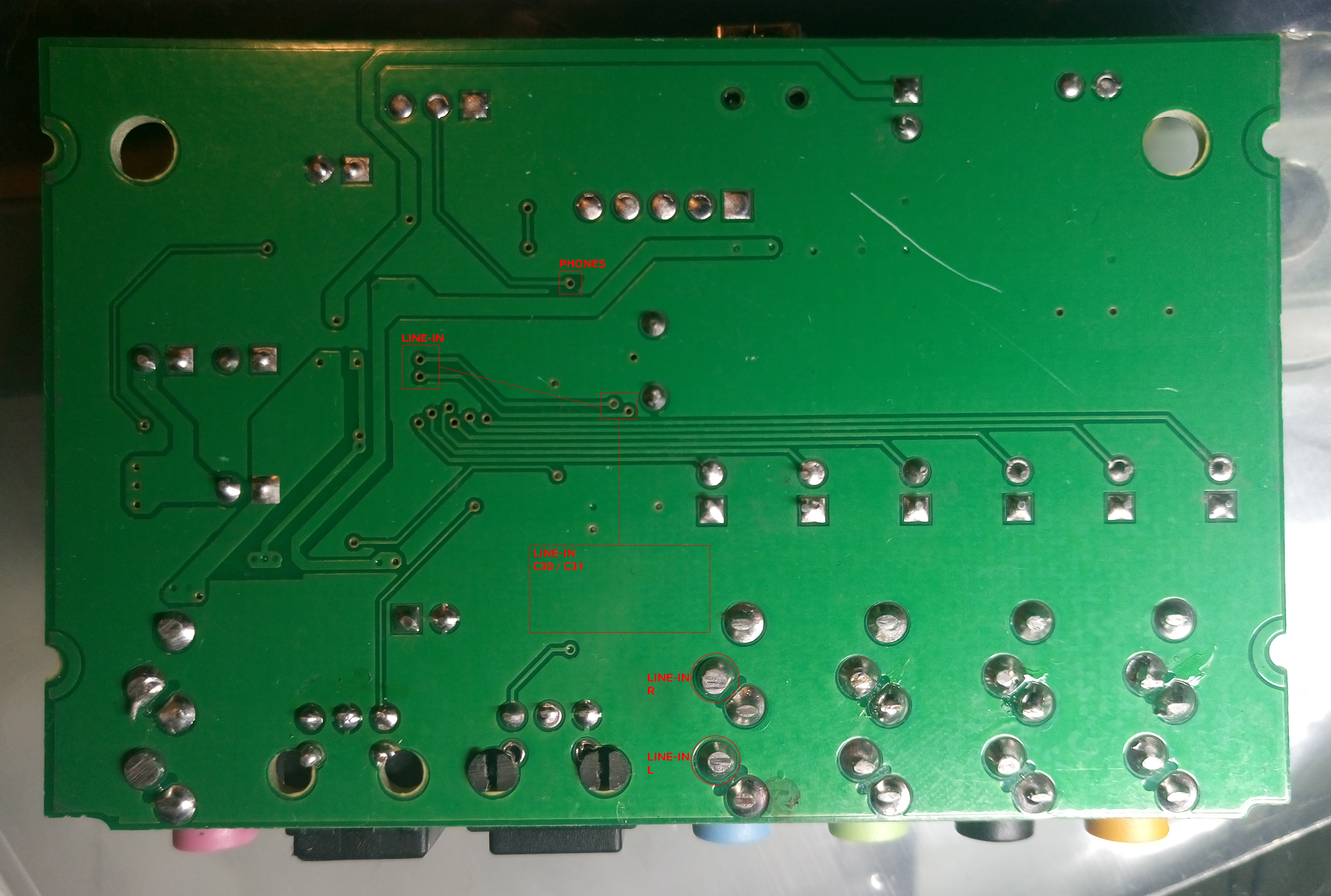
C-MEDIA CM6206 5.1 USB Audio Card – TOP & BOTTOM PCB Layers Overlay – Bottom Side (Horizontally Mirrored Photo)
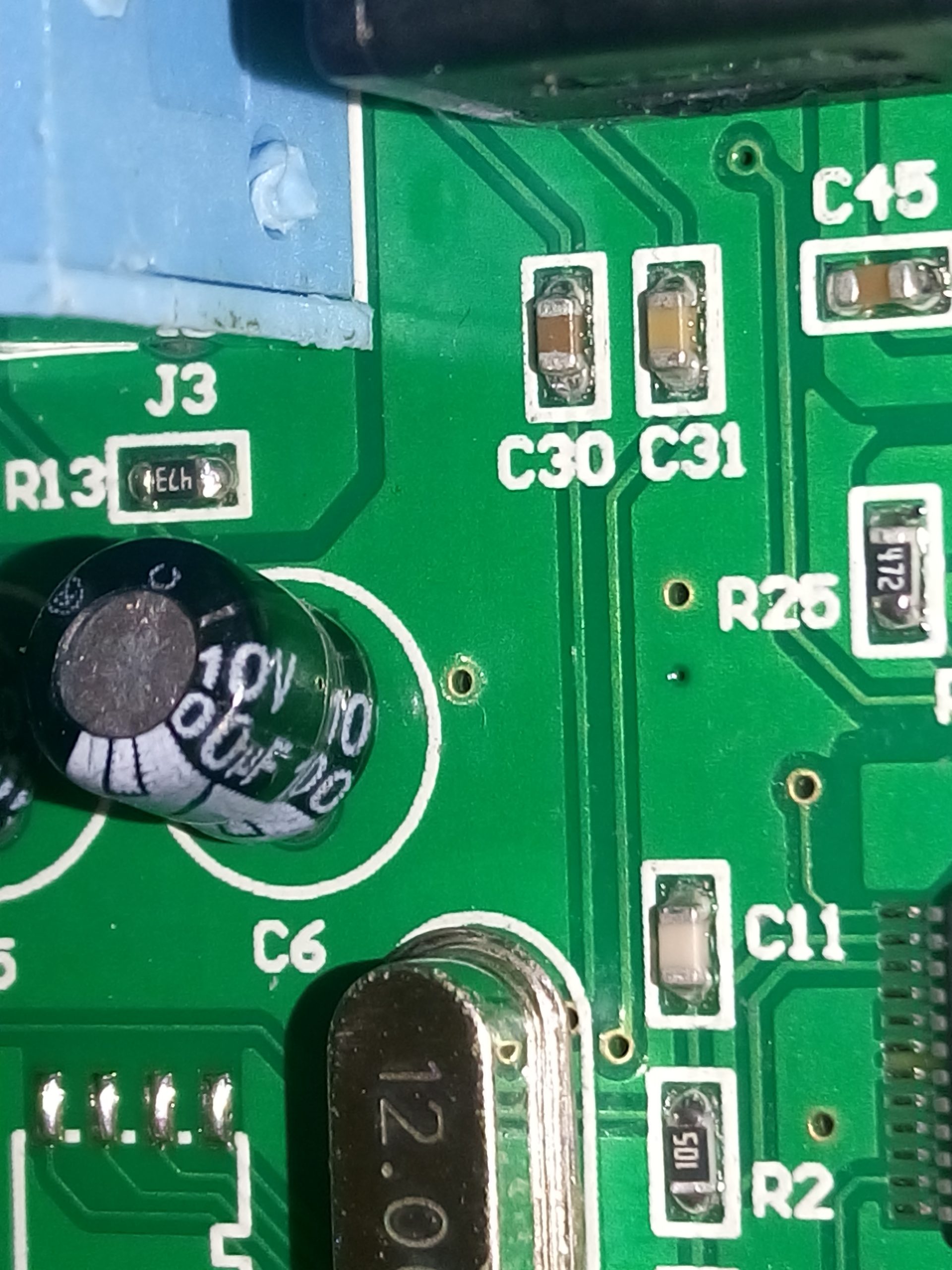
C-MEDIA CM6206 5.1 USB Audio Card – Line-In Input AC Coupling Capacitors Close-Up
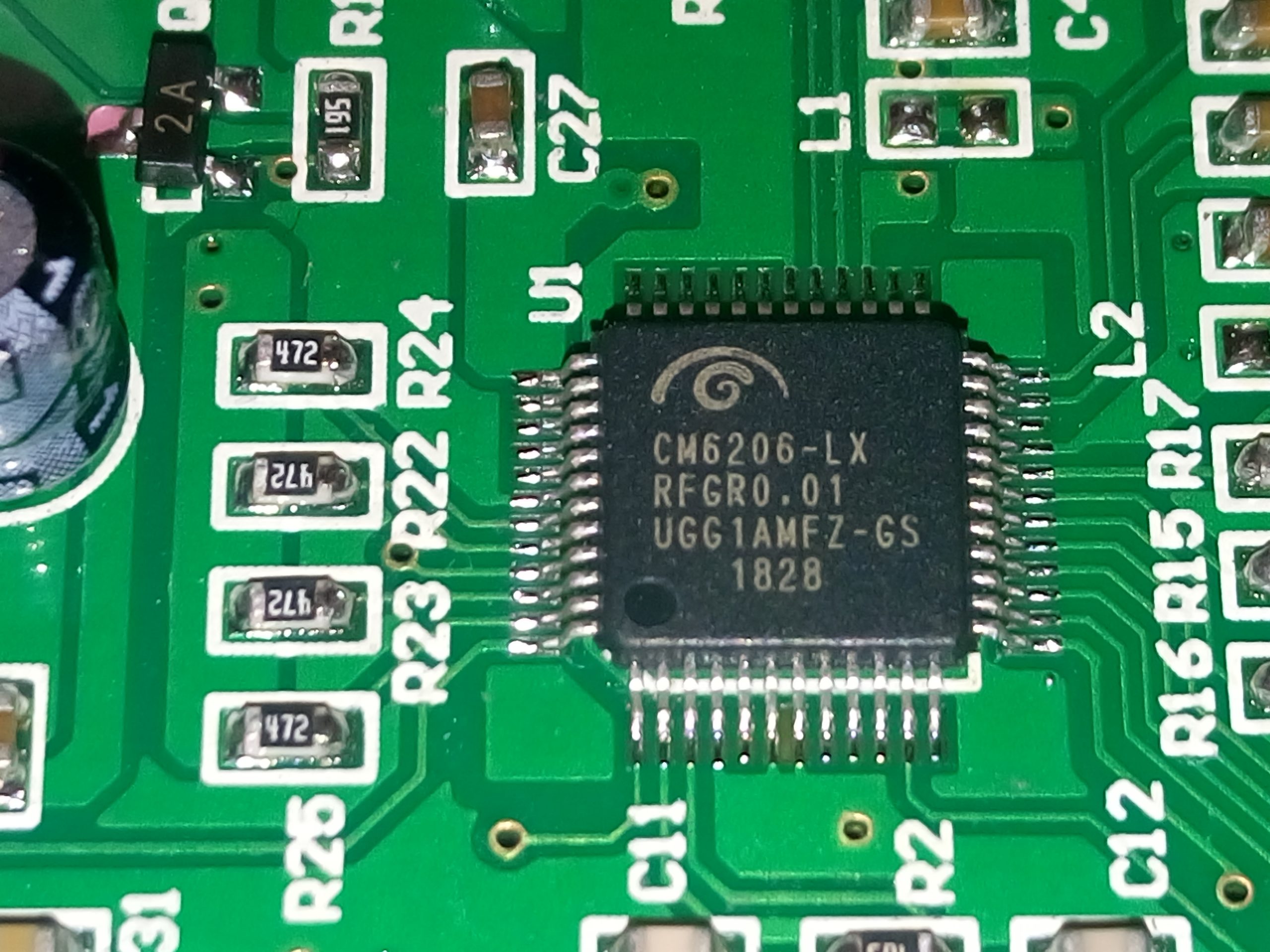
C-MEDIA CM6206-LX Chip Close-Up

I used solid capacitors with 2nd unit as they were much easier to solder than SMDs and have better electrical characteristics (performance)
Note: Outer “metal” case shell on solid (polymer) electrolytic capacitors is electrically non-conductive (in audio frequency range, at least — confirmed this with my own measurement), so it’s safe if they touch each other! If you still don’t have a piece of mind, you can very gently put a tiny sheet of paper or translucent plastic foil between them later after soldering (but it’s not really necessary) — just be careful not to rip apart SMDs from the PCB with too much force!
IMPORTANT NOTES & TIPS
MIC INPUT Frequency response without modification (ARTA FR1 CH loopback audio Mic-In <-> Line-Out)
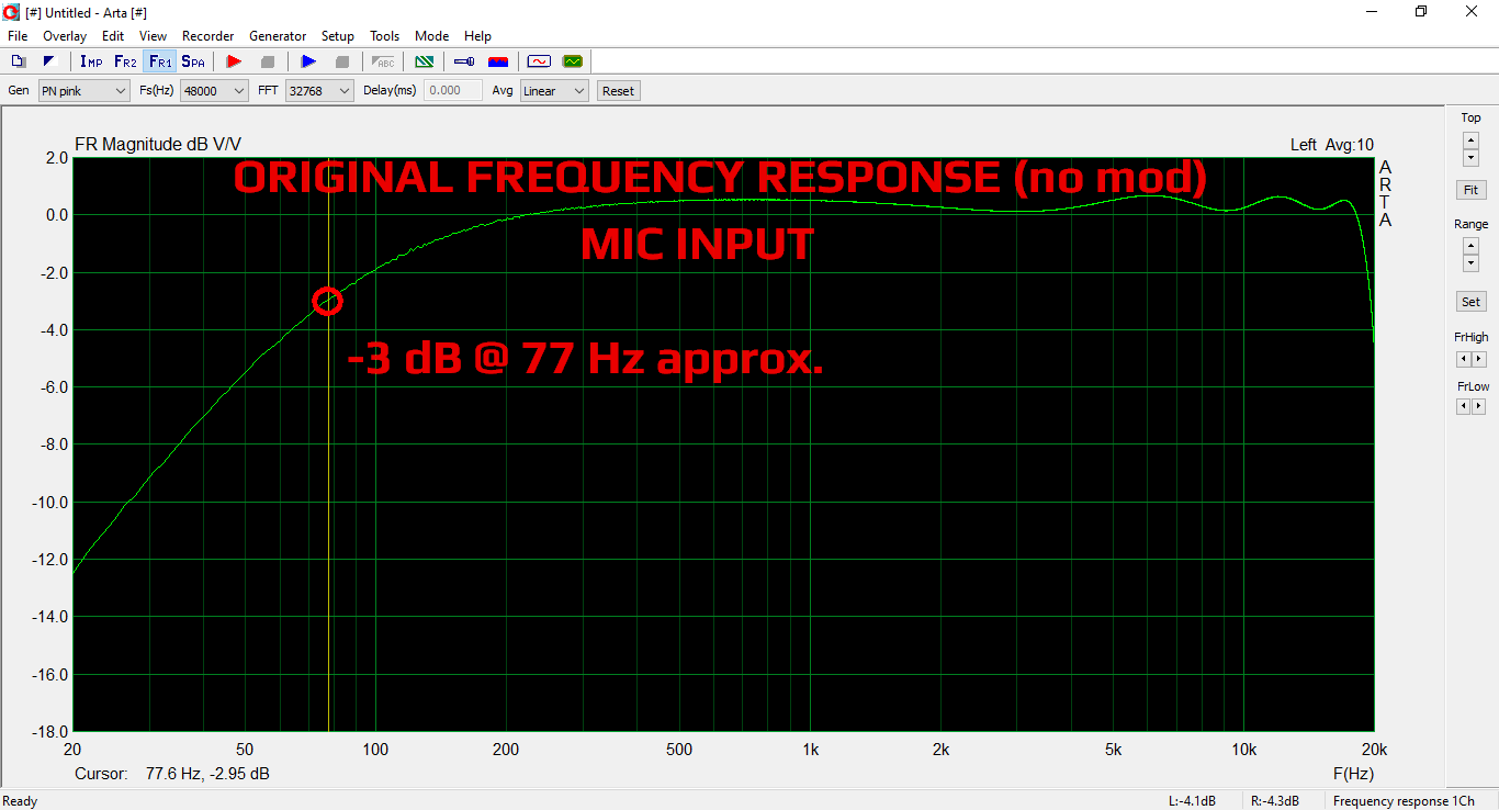
ARTA #1-1 C-MEDIA CM6206 5.1 USB Audio Card Mic-In ORIGINAL 20Hz-20kHz
Update: Well, it is not possible to measure MIC IN coupling capacitors capacity directly, but I have measured frequency response instead! And, yes, just as I suspected, undervalued 0.1 uF (100 nF) input coupling capacitors are used which results at approx. -3 dB @ 80 Hz point. In another words, you need to modify MIC input coupling capacitors as well if you plan to use them with higher quality microphone or simply wish to achieve better low frequency (bass) response with existing one.
DC offset can be compensated using Sound Forge or similar recording software with DC offset adjust compensation option enabled. Calibrated offset before each recording will help, but the drifting offset over time will still be present in some cases. Using some smart VST plug-in for post-processing should also help. FL Studio has a nice built-in factory DC remove effect called Fruity Center that works dynamically but it’s not enabled by default in newer versions, you must click on More plugins… in the Mixer channel FX slots menu and activate it in the list to make it visible/available.

C-MEDIA CM6206 5.1 USB Audio Card – DC Offset Calibration in Sound Forge 8 Recording Panel
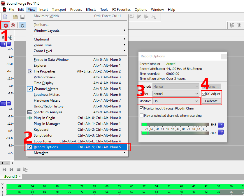
C-MEDIA CM6206 5.1 USB Audio Card – DC Offset Calibration in Sound Forge 11 Recording Panel
Another related issue which I discovered recently is that setting Windows 10 device slider for Line gain to 0 will not mute C-Media CM6206-LX USB sound card, only reduce gain to default predefined internal value! This means that for some devices such as CD players and audio cassette decks, which inherently do not have integrated output volume (gain) control knob, recording levels (= gain) may still be too high and you’ll need a passive attenuation resistor network in between your recording cables and C-MEDIA CM6206-LX USB audio card line input. See below recording for demonstration of such scenario where positive half-periods in recorded signal were clipped because of present DC offset, and input device (DENON cassette deck) does not have output level control knob.

C-MEDIA CM6206 5.1 USB Audio Card – Windows 10 Generic Drivers Line Input Gain Settings
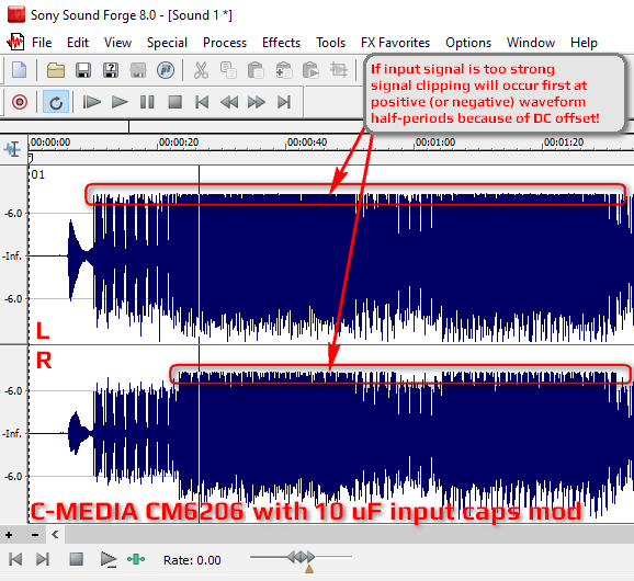
C-MEDIA CM6206 5.1 USB Audio Card – Asymmetrical Recording Clipping with DC Offset and Strong Input Signal
This isn’t something I’m particularly happy about to be completely honest and you should be extremely careful when making recordings via Line input port to avoid strong signals and potential waveform single-side or double-side uneven clipping and distortion because of the present DC offset. Using -3 dB safety margin should be OK, -6 dB if you wish to be extra safe and avoid unexpected peaks.
You should avoid recording at high levels near 0 dB (+/- 1.40 Volts) anyway, to avoid clipping. Remember, DC offset in audio is bad because it effectively reduces available dynamic range and maximum signal input voltage span.
CM6206-LX Volume Gain Control Resolution
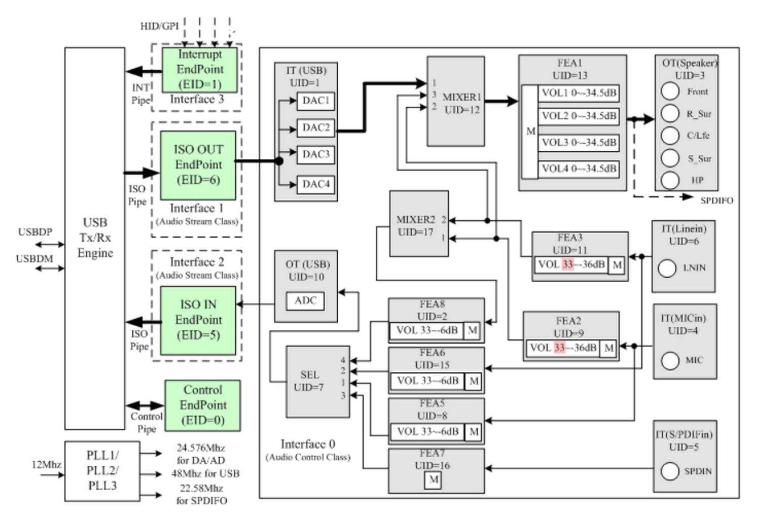
C-MEDIA CM6206-LX Block Diagram
Consulting official datasheet, volume controls and gain levels are:
- DAC Volume Control / Master Output (Playback) [Front/Surround/Headphones/SPDIFO]: from -34.5 dB to 0 dB plus MUTE state (38 linear steps / lin scale)
- ADC Volume Control [Line / Mic Input Gain] (Recording): from -6 dB to +33 dB plus MUTE state (26 x 1.5 dB steps / log scale)
- ADC Volume Control [Line / Mic Monitor Control Gain] (Playback): from -33 dB to +12 dB plus MUTE state (31 x 1.5 dB steps / log scale)
- ADC Analog Input Gain [Line / Mic]: from -36 dB to +33 dB (48 x 1.5 dB steps / log scale)
I have yet to test official C-MEDIA USB sound card drivers, which may be the key answer to solving the input gain control problem.
PART 2: C-MEDIA CM6206 5.1 USB Audio Card Headphones Line-Out Bass Frequency Extension Modification
So far, we have only modified Line-In inputs used to record/monitor analog electronic musical instruments or pair of high quality microphones (via preamplifier — not directly!). What about Line-Out (marked as FRONT OUT) outputs?

C-MEDIA CM6206 5.1 USB Audio Card – Output Coupling Capacitors
If you take a closer look at the output stage on the PCB board you will notice six 100 uF electrolytic coupling capacitors connected to their respective color-coded 3.5 mm output sockets. Each capacitor pair is dedicated for L+R main output (C5/C6), L+R rear surround output (C1/C2), and finally c/sub CENTER + SUBWOOFER output (C3/C4), respectively.
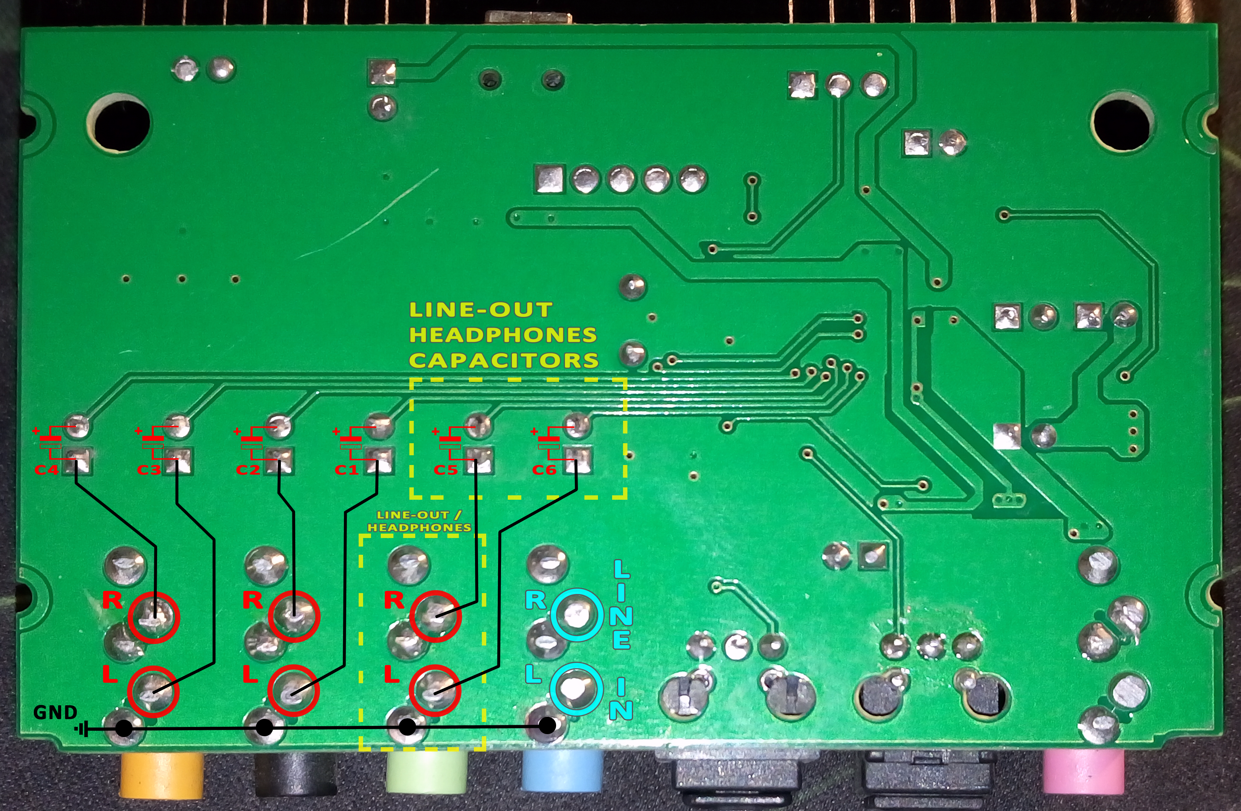
C-MEDIA CM6206 5.1 USB Audio Card – TOP & BOTTOM PCB Layers Overlay – Bottom – Headphones Line-Out Mod (NOTE: Corrected Output Coupling Capacitors Polarity!)
⚠️ If you take a closer look at the PCB board, you will notice that the output coupling electrolytic capacitors have their negative minus “-” terminals connected to the CM6206 chip’s side (pins). However, this is very wrong and illogical, because chip operates at single-ended USB +5.0 V power supply and output DC offset is biased at positive +1.40 volts, which allows AC audio signal to swing between 0 V and +2.80 V.
According to official CM6206 datasheet, output coupling capacitors should be connected with their positive “+” terminal at the CM6206 chip’s side, and this is exactly why we marked it as such in our annotated photo! The factory PCB version is technically wrong, and this negative -1.40 voltage will negatively impact capacitor’s life expectancy and performance. Because outputs are ended with 47 kOhms resistors to the ground, capacitors are constantly polarized with reverse voltage and current, even without any external load connected to the output sockets!
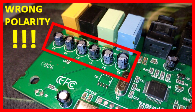
C-MEDIA CM6206 5.1 USB Audio Card – Output Coupling Capacitors WRONG POLARITY
Now, if your setup uses external audio amplifier or some other medium-to-high impedance equipment (e.g. 1k ~ 100k Ohms input impedance; CM6206 outputs are ended with 47 kOhm resistors), those 100 uF factory coupling capacitors will be more than adequate. Headphones with 64 Ohms impedance will be fine, and even most 32 Ohms models. Why? Well, most home headphones have issues reproducing frequencies lower than 40 Hz anyway (yes, they can reproduce them in Signal Generators, but in the real music mix those frequencies get lost because of poor frequency response and attenuation), so you will definitely not miss much without this modification.
Headphones with 32 Ohms nominal impedance and decent bass response such as EDIFIER H840 (they go all the way down to the useful 35 Hz in our tests) will be just fine with a -3 dB point at ~ 50 Hz (54 Hz measured in ARTA), but technically still far from Hi-Fi “on paper”. On the other hand, headphones such as SENNHEISER HD 201 won’t gain much because they cannot reproduce anything below 40 Hz properly (forget that 21 Hz from the official specification!). Still, if you test them with pure sine waves with signal generator, there is no doubt that 20 ~ 50 Hz range gets louder with larger coupling capacitors. And let’s not forget that your ears’ sensitivity to low frequencies, head physical profile and headphones anatomy equally play important role in low frequency response.
However, with ultra linear and low-impedance 16~24 Ohms headphones you will definitely notice some bass improvement because -3 dB point will be at 100 Hz and 65 Hz, respectively. Again, we stress out that your headphones must be real subwoofer monsters and linear all the way down to 20-25 Hz to notice any real difference, aside the measurement graphs! Otherwise, the effect of this Line-Out modification will be extremely subtle and barely noticeable if your headphones drivers cannot deliver.
How To Fix Line-Out Low Frequency Response with Low-Impedance Headphones?
Simply replace capacitors C5 and C6 with a higher value one. For 32 Ohms headphones use 1000 ~ 2200 uF / 6.3V, and for 16-24 Ohms headphones use 2200 ~ 4700 uF / 6.3 V electrolytic type. You can even use low-ESR types (usually used in switching power supplies) and solid aluminum electrolytic capacitors (usually more compact than ordinary wet electrolyte types; so you can easily squeeze larger capacity in a constrained space) for best possible audio performance, and low distortion.
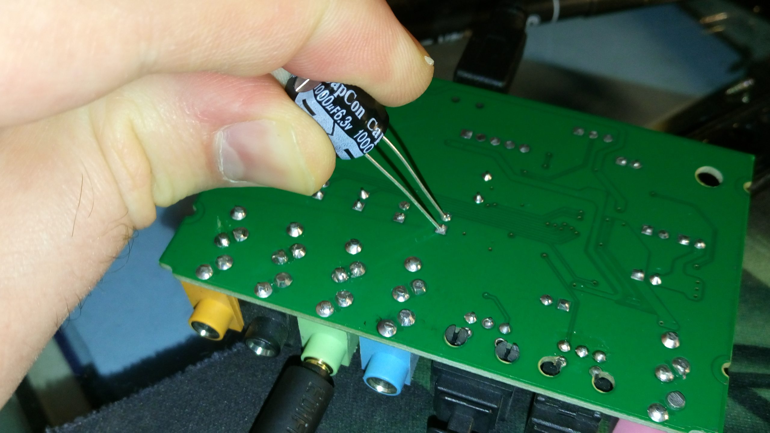
C-MEDIA CM6206 5.1 USB Audio Card – 1000 uF Line-Out Headphones Coupling Capacitor Mod Test
NOTE: Capacitors height must not exceed ~ 13 mm (1/2″ inch) or you’ll have to position them horizontally in order to be able to put aluminum enclosure back. Distance (pitch) between capacitor’s leads (pins or “legs”) is 2.54 mm ideally, but you can bend larger 3.5 mm / 5.0 mm types easily.
C-MEDIA CM6206 Line-Out Modification Measurements
[1] without modification + EDIFIER H840 (32 Ohms) headphones load connected @ output
(ARTA FR1 CH loopback audio Line-In <-> Line-Out) (Line-In 1 uF input capacitor mod applied)
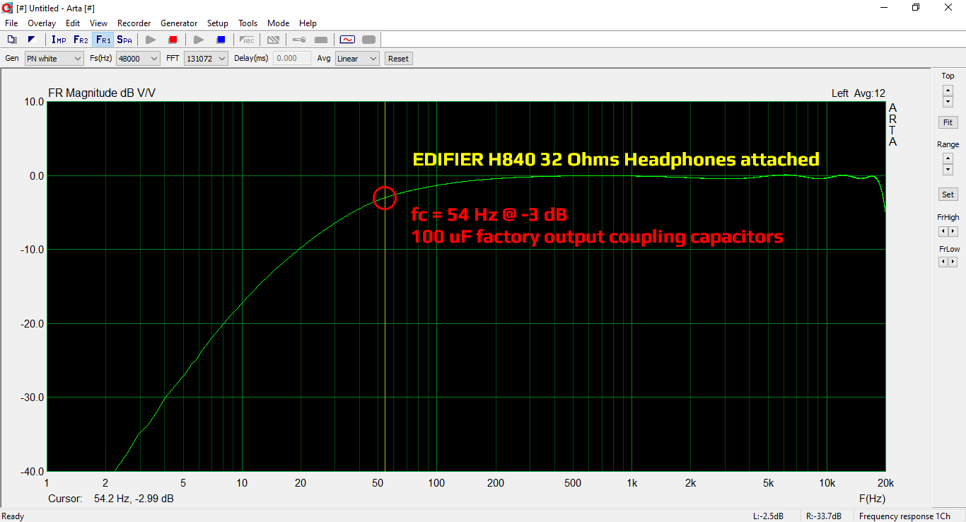
ARTA #4-1 C-MEDIA CM6206 5.1 USB Audio Card Line-Out + EDIFIER H840 + 100 uF Capacitor Factory -3dB Marker
[2] with 1000 uF capacitors modification + EDIFIER H840 (32 Ohms) headphones load connected @ output
(ARTA FR1 CH loopback audio Line-In <-> Line-Out) (Line-In 1 uF input capacitor mod applied)
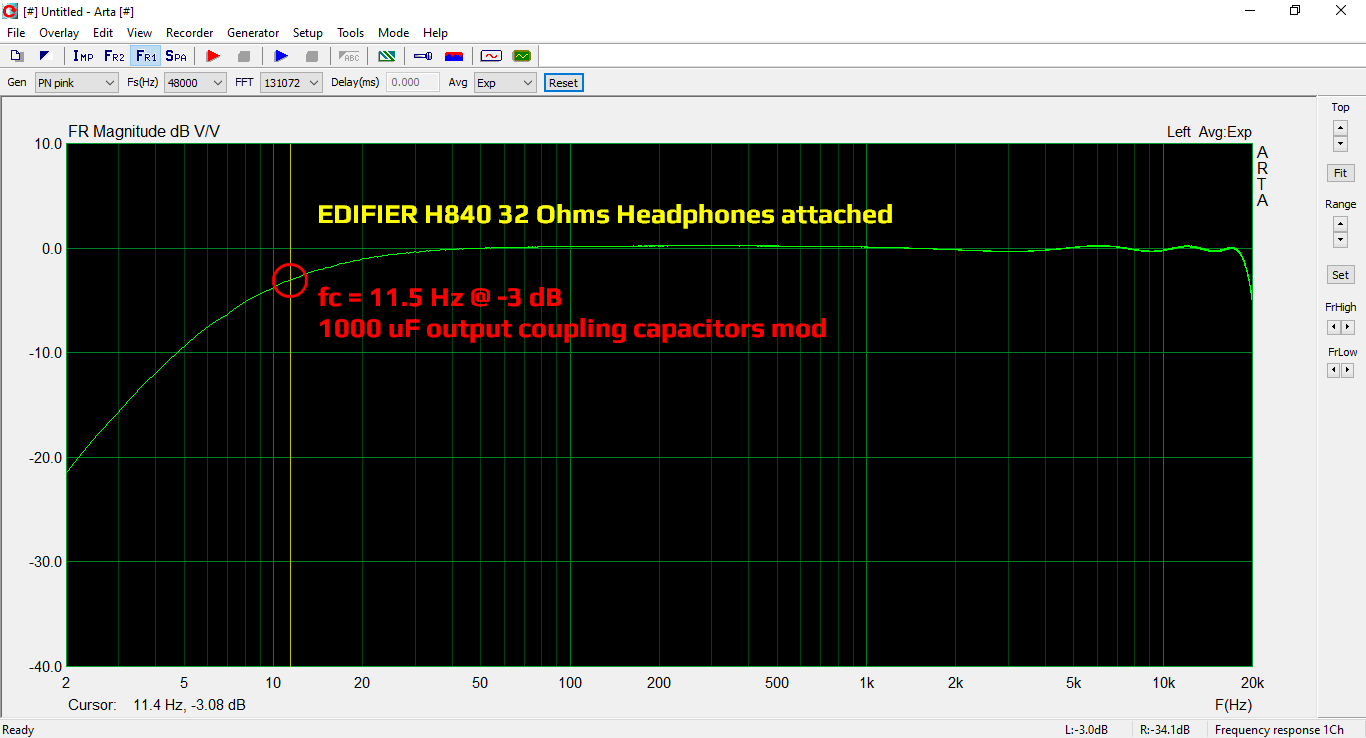
ARTA #4-2 C-MEDIA CM6206 5.1 USB Audio Card Line-Out + EDIFIER H840 + 1000 uF Capacitor Mod -3dB Marker


![Xiaomi App - How To Re-Install Stock Factory Version - How To Fix Corrupted Gallery App [no root]](https://tehnoblog.org/wp-content/uploads/2025/09/Xiaomi-Gallery-App-Code-Bugs-Artwork-1024x576.png)


37 Comments
Add Your CommentHello! I’ve found your article on the net, and it helped A LOT with such cheap external USB audio board! I was planning to use this USB audio adapter for REW measurements, but its -3db low frequency started at 209Hz! Impossible to use… Measuring the input coupling capacitors, I’ve found something near 71nF, as per your calculations it should give -3db roughly at 112Hz… no problems with calculations, as there are many uncertainties, but it gave me a hint, at least… I’ve replaced those capacitors by 4,7uF, and could measure -3db at 2,6Hz… fantastic, just what I was needing (my measurements will no go lower than 10Hz…). Thank you, specially for your analysis of this problem! BTW, my board has CM6206-LX version, I’m not sure if this can make any difference from CM6206… Congratulations, and keep going! (I did not alter outputs, as they are not to be connect to low impedance equipment)
April 24th, 2021Great! Thanks :)
If you take a closer look at high resolution photos above CM6206-LX is also stamped on our chip as well, but it’s usually designated simply as CM6206 (e.g. in PDF datasheet), so we dropped -LX part for simplicity. Could be a chip technology or package designation.
There’s also a CM6208 (CM6208-LX) chip in same LQFP 48 pin package, and it also has 7.1 (8 CH) analog outputs (DACs), it seems that they are different revisions of the exact same chip.
This modification can be applied to 7.1 Audio Cards with C-MEDIA codecs and any other card with poor frequency response.
April 24th, 2021Question, what 4.7 uF – what value do you need?
May 26th, 2021Another question, do you need to change the microphone capacitors, with what value? Thank you!
Hi, I do not fully understand your first question.
1) For input capacitors, yes, a value of 4.7 uF is fine, and voltage rating should be 6.3 Volts or higher (SMD types are usually limited to 6.3 ~ 10 Volts). Type should be ceramic or non-polar, but as you can see from one screenshot posted above, you can even use low-ESR solid electrolytic types without problems.
Please watch video tutorial for clearer understanding.
2) I haven’t modified microphone input capacitors, that is just mentioned as a possibility — it is up to you. If you plan to use higher quality microphone or achieve more linear input response, then my answer is — YES in that case, you have to modify input MIC capacitors.
What value should you use? Exactly the same as for the LINE inputs! A value of 4.7 uF (or 10 uF) should be fine, and everything said for LINE IN caps above is valid in this case, as well.
Remember, CM6206 recording inputs are exactly the same for both MIC IN and LINE IN (ok, the basic analog circuit part, at least, let’s ignore MIC GAIN boost capability for the moment), it does not really care what device you connect to it. However, what does make MIC input(s) so special is the outer DC bias circuit, and the fact that in this cheap 5.1 model both L and R microphone inputs are connected to the one and only MONO microphone via C16 and C17, as explained in the article. The reason why it’s only MONO is because a standard 3.5 mm jack has only 3 rings: Common (ground), Microphone signal and DC voltage bias.
3) Output capacitors are low-ESR solid electrolytic types, because you need large capacity. Voltage rating is, again, 6.3 Volts or higher.
May 26th, 2021Sorry, I didn’t pronounce it correctly, 6.3 volt was the answer.
I want to use it to measure some speakers, and TS parameters, with Art / Limp, Rew. I use a Dayton imm-6 microphone for measurement. I also have others calibrated, but I wanted to compare after replacing the capacitors with a Presonus card of 100 Euro + microphone Sonarworks ref 20, calibrated.
Sorry for my bad English, I use google translate.
May 26th, 2021No problem, I’ve suspected that you meant “volt” (voltage), so that’s why I mentioned it in my answer.
Yes, this modification will suit you well, I also use it for impedance measurements (LIMP) and frequency response tests (ARTA), as well. You will get +/- 0.3 dB flat frequency response, and you can later subtract it from the measurements to achieve even greater accuracy. Good luck!
May 26th, 2021Ok, thanks for the answers, if I can’t handle something, I’ll post here.
May 26th, 2021Hi. I stumbled upon your blog after a very long research about this product because I am looking to make work its digital output. At first W10 installed it automatically but no redlight was coming out of the output so I installed the W8 driver: now it shows the redlight and my AMP plays sound but it only detects Stereo signal. I changed my audio setup on windows to 5.1 but it always send only the Left and Right channels. The weird thing here is that if I go to the audio device properties there is a checkbox to activate Dolby Digital, if I select it it sends REAL Dolby Digital 5.1 sound with a short audio test that plays every speaker with a bell sound, and my AMP also shows that it is receiving 5.1 sound signal, but that’s the only time this soundcard really sends Dolby Digital sound through optical out. I would appreciate that you could share if it works for you and how, thanks in advance!
July 11th, 2021Hi, sorry, I didn’t check digital outputs, bought it only because of analog LINE inputs which I needed.
You should install official C-MEDIA drivers from the accompanying disc, or download them from internet and see if that helps resolve multi-channel digital audio output.
July 21st, 2021If you want Dolby Digital or DTS output from this card then installing the original software is recommended, then you have to enable it under the digital output’s properties. Finally, most important of all, the media player you’re using must be able to either select AC3 (Dolby Digital) or DTS audio track AND support “SPDIF passtrough”.
Windows 10’s builtin player can do passtrough given the correct format, but so far only MPV has been able to *reencode* any 5.1 to AC3 (if it’s missing) and send it over Toslink to my speakers.
January 2nd, 2022Hi! Thanks for your upgrade recommendation. They are helpful. My question is whether film capacitors like WIMA MKP (polypropylene) would be a better alternative to electrolytic caps? They are not prone to aging and are actually more often used in high-grade audio applications.Thanks!
September 15th, 2021WIMA MKP are very expensive audio grade capacitors, usually used in analog crossovers (x-overs) for speakers, and other demanding applications. They have very little distortion (they are extremely linear), and if you don’t have money for those, then there are also excellent but cheaper audio grade axial caps you can purchase on AliExpress and Banggood (I had good experience so far).
However, there is always but: you will literally waste your money. Why? Well, first of all, those output ELCOs are just there for AC/DC coupling. They won’t make any noticeable / audible difference whatsoever. It kind of doesn’t make sense to put two or six $1 caps at the output, when total cost of entire audio card is something like $5 or $10. Right? And, besides, you won’t hear any difference! I promise you that, unless you have superhuman super-linear hearing of a sort. Which you don’t, especially if you are 30+ years old (natural human hearing progressively degrades with age).
For the low signal coupling inputs, again, yes, in theory, those MKPs (or cheaper MKTs) would be great, but they do not affect the signal much beyond the inherent high-pass filtering (RC resonant circuit), and because the signal is low power kind, losses in capacitors are your least concern.
You cannot improve AD and DA converters merely by upgrading input or output coupling capacitors! The signal will still be the same, limited by converter precision, quantization noise, jitter etc. Bottom line, buy another more powerful DSP audio card, instead of capacitors in that case. You will just waste your money on the wrong items otherwise.
MKP caps are also physically larger, because they use bigger cross sectional area (those low dielectric losses must be “paid” somehow – you seriously don’t expect a free lunch?), which is another issue to consider – is there enough room to put them in place of electrolytic caps with matched capacitance? I doubt it. In fact, you won’t find MKPs in the range of 1000 uF ~ 4700 uF! Aluminum solid low-ESR capacitors are just fine (read perfect) in this case. Period.
Bottom line, expensive MKP capacitors are justified in applications like high powered high signal speaker crossovers. However, even in those applications there is a reasonable limit – shelling out $250 for a single high-end MKP capacitor is much closer to insanity and bragging, then real benefits. I would suggest reading this excellent forum post at audiosciencereview.com.
Hope this helps.
September 15th, 2021I got this thing to cheaply record from SPDIF to my laptop – but SPDIF in doesn’t work? Also it’s noisy, very noisy both recording and playback. I sorta skimmed over this but did not see anything about regarding noise. My board is slightly different from yours, has surface mount output caps (also put in reversed) but I believe is otherwise the same. Now If u notice the -LX specs 5V for both analog and digital power.. Yet there is a fixed 3.3V 3pin regulator (AMS1117-3.3) which actually feeds the power pins 27-AVDD1 and 37-AVDD2, which are in the spec marked as requiring 5V. I thought well maybe the datasheet i have is wrong, but since the SPDIF optical reciever (DLR1151) is also spec’d at 5V yet powered by 3.3V and the optical transmitter is noticably dimmer than anything else i have and powered by the same 3.3V – well just wth?!? The board looks professionally designed by someone with a little experience. Lack of seperate digital vs. analog grounding seems a little amature but still it’s flooded on both sides so shouldnt be too bad i think it’s probably feeding the analog section with 3.3V instead of 5V thats causing the noise.
I’m a broken broke bish atm and have no income and no solder therefore have not yet tried to correct these problems but thought i’d point it out in case others having noise or SPDIF issues come across this as i did.
Actually I really want to bypass the optical reciever anyways since my synth has coaxial output (use converter i made years ago). so jaja… i bet this wont even post cause rly nothing works anymore it seems.
September 30th, 2021Hi, thanks for the comment. I can’t really help you with SPDIF because I don’t use them at all, really. Yes, the analog section seems to be running from 3.3 V, but except for limited output voltage swing (set at around +1.4 V without input signal gives about +/- 1.4 V range), that could be the limiting factor. Some user at YouTube (comments under my video posted above) also had issues with garbled sound, and he ‘fixed’ it by ordering a new card, as it turned out, the first one was faulty.
I would suggest to try drivers that come with this card on a mini disc (mini CD), that should at least give you native control over SPDIF and gain, something which seems not possible with generic USB Audio drivers (assuming you use Windows, but it could be the same issue on Linux and Mac).
It’s a shame really, because the chip has a nice potential, but the software part is not that great. When I find time I’ll give it a go with the software part that comes with it and see if it makes any difference to the gain control and such.
Bottom line, Realtek chips are much better and higher quality than C-Media, but I don’t know if external USB Audio cards are available that are built with it. Sound quality (at least, for the analog Line In part) is just better, output frequency response is dead flat, and software is great.
September 30th, 2021The version in blue case I bought on Ebay several years had a SPDIF-out component in the SPDIF-in place, once I soldered in an SPDIF-in component, I was able to record from SPDIF-in using Linux.
November 19th, 2021Try replacing both ceramic and polymer capacitors at line input with film. There are relatively small and inexpensive 63v models available. It can significantly reduce input dc offset due to much lower leakage current of such caps.
March 21st, 2022Thanks! However, polyester film capacitors have lower capacitance density, so they are bulkier in size in comparison to high-quality ELCOs. Also, they are usually produced for higher voltages, e.g. as you mentioned 63V being the lowest commercially (off the shelf) available values, and usually 1 uF is the largest one you could theoretically squeeze into tiny space using ~ 5 mm pitch MKT caps.
Another thing is that DC offset is probably caused by poorly balanced (uncompensated) input stage inside C-MEDIA chip itself, and I seriously doubt that external capacitor alone can eliminate it or make a noticeable improvement, but I could be wrong.
March 21st, 2022The other reason to remove MLCC caps is signal distortion near the cutoff frequency (more on this in SLYT796 by TI). As to electrolytic caps – they show much better performance if DC biased (which is not the case for most signal sources).
March 22nd, 2022Hi, thanks for that document. Yes, using polypropylene MKP capacitors for audio applications is the best choice (check above my reply to Alex’s question), however, as I already mentioned, price-performance and space constraints must be taken into account in this case.
Also, I personally really doubt there would be any sound difference (all measurements aside, but also because 10 uF Low ESR ELCO will put -3 dB resonant frequency below 2 Hz, and won’t really care about signal in that frequency band, unless use it for measurement).
Plus, C-MEDIA chip isn’t really something you should spend more money than what it’s worth. In another words, if you really need lowest possible THD, and proper input coupling, low DC offset etc. then you should look in another direction, e.g. more expensive sound cards on the market.
As I mentioned, modern Realtek chips are far superior to C-MEDIA, but I am unaware of any cheap mass-produced external sound cards that use them. It’s a shame, really.
Regards
March 22nd, 2022Hi! I use this 5.1 sound card to connect to my phone with “Adapter usb camera otg to lightning”. I tried using its “line in” input for stereo recording. However it has no signal. This is like when connecting the usb otg to the phone, there is a program that prioritizes “mic-in” first and not “Line-In”. I downloaded the N-track application on the Iphone App Store to switch from “mic-in” to “line-in”, it had stereo sound, but it was a bit cumbersome. I would like to ask is there a way to remove “mic-in” or prioritize “line-in” instead of “mic in” when connecting to the phone without having to use a converter application?
October 11th, 2022Hi, I don’t really know, someone with more experience can post solution if it exists. Honestly, you should be happy that it actually works at all on your phone. This card does not work properly at all on my Android (Xiaomi), it is recognized, SPDIF LED is working, but no sound comes through.
Update: But it actually works for recording on Android, however, only for Mic input. So, yes, I can confirm that Mic is the default input on this card, and, at least on Android, you can’t record via Line-In (tested with WaveEditor app using both System and app’s own audio routing functions). I don’t have time to check other recording apps and phones, some might actually support Line-In directly with this card, but once again, driver support is the real problem here.
October 11th, 2022On the version of the PCB that I have, C14 is not populated. I can see from your photos it is present, but from the angle the photos are taken I cannot read the value from them. Could you tell me what is fitted to C14 on your PCB?
December 6th, 2022All ELCOs are the same: 100 uF / 10V
December 6th, 2022(C1 ~ C6, C14, C15, C25, C29, C44, C47)
Thank you for the great post! I got one of those units in a thrift store for $1 and it’s really convenient for travel! I will look to do the smaller capacitor on-top mod as that seems easiest to get down to that 1hz response.
December 30th, 2023Hello, if you still alive, i have a question. If not i will find an answer by brute force and ignorance.
I recently got one of those, revised model on smaller pcb. But it works funny with program called REW. line in and microphopne show both som cosmic noise level which is constant flat line around half the height of the graph. So frequency response becoming kind of irrelevant unless this got fixed. Obviously optical in is silent.
Is there a reference schematic of this device somewhere?
February 3rd, 2025Hello, I don’t have time now to check REW (used it years ago), but it seems like a DC offset issue described in the article. It is a problem of the ADC and you have to compensate it in software somehow. Check REW preferences and activate High pass box to have REW automatically apply a 2 Hz high pass filter.
February 3rd, 2025Well 3,5uf caps on the line input help with bandwidth on new model too, the pcb is now almost all smd, but caps are still backward and there is less of them.
Aplying bandwidth filter helps in REW but i have no idea what frequency it cuts out but it cuts noise from -30 dbfs to -75 and -83 for line in L and R channels while microphone input gets cut to -85 on both L and R channels
on the other hand drivers provided with the device seems to work worse than with no drivers at all
i will have to dig deeper into it, fully digest the article (which might be a bit tricky because english is not my first language)
thanks for help
February 4th, 2025About that drifting input buisness. I been thinking about it, and the answer always was reference the input to ground by a resistor. So i checked how other sound card do it.
February 5th, 2025For instance lm4550 in it’s reference documentation uses 6,8k resistors one to ground one to capacitor and input goes in the middle. so i did just that and i don’t see any inverse effect of it. the bandwidth and sensitivity seems to be the same in rew, And i did tested it with signals from headphone jack of the laptop that can do 0hz flatline up to 25 khz at 192khz sampling rate and the adc in the cmedia ploted very nice flat line from 5hz to the very end of bandwidth
Input inpedance might got a major hit. noise levels stay the same.
For my acoustic measurments it seems to be enough, it traces speaker impedances better than a pc trough my silly little measurment jig. i would love to use my laptop flat adc and dac together but it has only one jack for mic and speakers combo and i need 2 input channels for the measurements
Nice catch about DC biasing inputs with resistors!
Of course there are 4.7 kOhm (or 47 kOhm? CMEDIA PDF datasheet is soo low-res) pull-down resistors at the input Line-In stage in CMEDIA reference design (after the input capacitors, though), which are not present in this device!
This audio board has several key design errors, it’s such a shame, really. It could be great budget instrument for $5, but it can be saved with relatively simple modifications if you can deal with small space and SMD components around. However, it seems that it was designed mainly as a cheap 6-CH surround card, and Line-In recording feature was just an after-thought.
February 5th, 2025It would make more sense as 47k because stated input impedance is around 20k.
the thing is i can’t even find the schematic. In online datasheet databases are mostly updated documentation booklets without schematics. ot am i blind.
And as for small components, nah. While flipping output caps i riped one pad from the cap on the controller side, so i drilled a hole trough the board and connected it to a trace on the other side :] and also i used 220uf caps because i thought low frequency response might improve. It didn’t :P As for input capacitors and resistors. I desoldered blue jack socket pass trough the holes 2 1/4W tht resistors and put the socket back, on the back side i soldered 2 more resistors to the ground of green and blue sockets. on the top i soldered big smd capacitors standing upright on the pads and soldered resistors from the socket on top.
February 5th, 2025The case still closes i have no issue with it looking ugly inside, since it works.
Thank you for sharing this valuable info, nice work! Regarding schematic, check the official CMEDIA CM6206 datasheet – application circuit section on pages 35/36.
February 5th, 2025Thanks for answering & giving solutions to all the queries!
August 18th, 2025I have this same dac, planning to use 4.7 uf / 50V rifa film capacitors externally (as they are chunky), so fitting everything in a bigger case. my concern is 4.7uf ok for flat freq response?
Hi, as shown in the table at the end of the YouTube video, 4.7 uF will give you 1.7 Hz cut-off frequency (-3 dB), which in turn should give flat response from 20 Hz and above, so the answer is – yes.
August 18th, 2025Opps I missed it while scrolling
August 20th, 2025So I can replace all electro capacitors in reverse polarity with eight 4.7uF film , except mic as I don’t use it
Btw I checked 5.1 ch with Saving Private Ryan” , they work perfectly in VLC on Win10 . Also I played stereo flac files with multi ch. option + room effects enabled. It kinda worked ok.
On Rasperry Pi + OSMC OS. , only 2 ch setup works for flac stereo.
One more request, can you make a tutorial for headphone jack , volume control , dual mono mic mod please
Thanks
No, output capacitors should not be lower than factory values (100 uF), but ideally they should be at least 1000 uF, as explained in second section of the article. I thought you are referring to the input capacitors where 4.7 uF should be fine.
If you don’t need low impedance headphones output, e.g. you are connecting the card directly to the line inputs of your amplifier (10 kOhm input impedance or higher), then 4.7 uF will be fine, but so will be with current capacitors.
August 20th, 2025I will be connecting all the outputs to an external power amplifier (6 ch. AVR analog IN).. This is my attempt to bypass the AVR’s non repairable HDMI card (infamous for Cinema DSP TI chip failure).I will also solder a red LED (D1) Btw any ideas about the optional sop IC (U2) not soldered on the board ? Thanks
August 21st, 2025Not sure you will gain anything by replacing those output caps in that case tbh. Regarding U2 chip, the connections seems to go to pins 14-17 EEPROM interface signals.
August 21st, 2025